


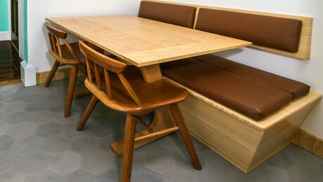
The desk I simply completed constructing relies on a joint I’ve been calling the “teamwork joint” for about 20 years. It was impressed by a poster I noticed on the wall at an advert company method again when. It seemed one thing like this one:

The meeting is just about 4 long-grain butt joints, generally assembled with nails or screws. I made storage items, stools, rotating show cupboards, and desktop storage items however by no means used it for “actual furnishings” till now.
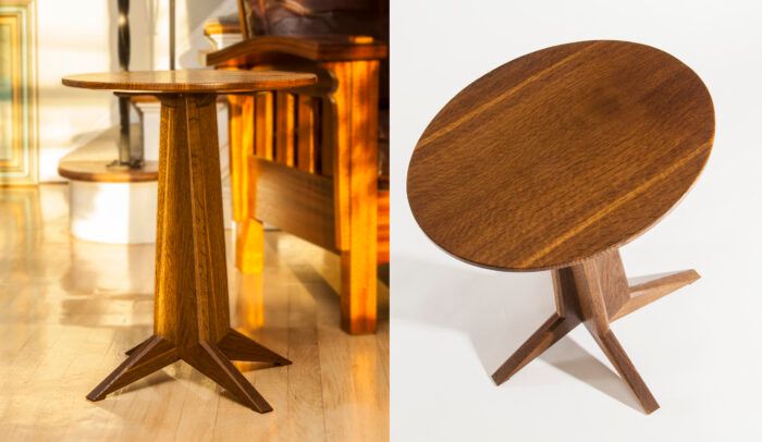
This small oval facet desk began conceptually as a Shaker stand in a Scandinavian or Craftsman model. I wished to make the bottom “oval” like the highest by various the lengths of the legs whereas sticking with a symmetrical column pedestal design. As I sketched I knew I wished to boost the desk off the bottom like a shaker stand and didn’t need to get too far into the rectilinear stick-ly facet of Craftsman. Introducing angles appeared to assist. My first draft of the desk at quarter-scale was promising.

With the column tapering and the legs splaying at completely different angles, there was an attention-grabbing motion as you walked round it. Making the mannequin taught me that the problem could be in getting the lengthy and brief legs descending at completely different angles to the touch down collectively. I labored up a scale drawing and roughed out the steps of my course of. On this publish I’ll present you ways I make the components for the desk’s base.
Prototyping the desk

Planning on making two tables, I checked the wooden stash and located a white oak board 6/4 by 11 in. by 8 ft. It had some lengthy checks in it, however the desk components had been slim and brief, so it made the grade with sufficient for each bases. I additionally pulled a 5/4 by 11-in. by 5-ft. poplar plank to make use of for my prototype. After a day of milling, I had the components for 3 bases. I put the oak apart and constructed the poplar desk with a recycled beech prime. It went properly and helped outline the jigs and refine the method. On to the oak …

The desk as drawn stands 22 in. tall with an 18-in. by 15-in. oval prime. The legs span 20 in. on the lengthy axis and 17 in. on the brief. There’s forgiveness within the course of; lacking the leg angles barely received’t have an effect on the desk’s stability. You’ll see why later.
Jigs
The construct revolves round 4 jigs. The primary tapers the central column components, the second and third taper the legs and assist with the ft. The final jig is the important thing to the construct. Jig #4 permits chopping the ft of the lengthy legs AND brief legs to type the foot pads, all on the similar peak from the underside of the column to the ground.
If you have already got a tapering jig, you need to use it to chop the primary column tapers. Should you resolve to construct the desk for a spherical or sq. prime and wish the legs to be symmetrical, you’ll solely want one leg jig.

Begin the column jig with a base panel about 6 in. by 24 in. Mark the ends of a column clean at 1.5 in. and three in., and lay it on the bottom of the column jig. Clamp it in place and add a protracted backstop to the bottom that strains up with the 3-in. finish of the clean. Safe it to the bottom. Double-stick tape will work, however I screw them down onerous as a result of I exploit toggle clamps. Add a base cease block and the jig is finished. Cosy the jig to the desk noticed blade and minimize the tapers on the column blanks.

Make the 2 leg jigs the identical method utilizing the angles from the drawing. Their bases are all 6 in. by 11 in.
The entire components on the cutlist ought to be milled 4-square to start out; with all the pieces squared up there are fewer methods for issues to go improper. The leg blanks will produce two legs every, with the long-grain edges serving as reference surfaces through the construct. The matching components are interchangeable for now. Mill up your blanks and both make a couple of extras or make a pair from plywood or scrap for take a look at cuts. Making the leg blanks longer provides room for error.
Mark every reference nook if you put it right into a jig to make a minimize. The components will get extra irregular in form as you progress and errors will get simpler. Set your rip fence to the sting of the column jig, and taper all 4 plus the additional take a look at clean. Save the offcuts to make use of later as clamping cauls.
At 4 in. huge the leg blanks have some additional meat on them. Use the additional/scrap clean to sneak up on a minimize that reduces the dimensions of the waste between the legs. (4 an identical legs might get the waste to zero.)

The leg cuts will NOT be on the sting of the jig; they are going to overhang it by about 3/8 in. This additional materials will type the integral footpads afterward.

With the components all tapered, arrange for some angled finish cuts. Use no matter you’ve got that may produce sq., repeatable cuts. Repeatable is extra essential than correct right here. Having the blanks match one another is extra essential than hitting the angles completely. I did some fine-tuning to get my chopper squared up; all it took was a airplane shaving inserted within the 90° cease.

Arrange for a 30° minimize inserting the nontapered reference fringe of a column clean in opposition to the fence and a cease at 19-1/2 in. Earlier than you alter the noticed setting, minimize a block of something about the identical thickness to the identical angle to make use of in constructing jig#4. The angled face for the jig ought to be at the least 5 in. huge.

Change the noticed angle and minimize the leg angles to maximise their size. I double-stick-taped a cease to the floor of the chopsaw. Reduce the brief legs at 42° and the lengthy ones at 46°. Once more, ensure that they’re sq. cuts and match one another. The angles ought to be shut however are usually not crucial.
Use the cutoff you made on the 30° column angle to construct jig #4. The jig has a small base block and the 30° block dealing with the blade. Mount a leg clean and sneak up on a minimize that leaves you a few 1-in. flat for the foot pad. Earlier than taking the primary leg out of the jig, make a registration mark the place the highest of the foot (which is the within of the “ankle”) lands on the jig.

The remainder of the blanks go into the jig aligned to the mark. That is the place the TOP OF THE LEG MEETS THE COLUMN—not in opposition to the bottom of the jig. With out shifting the fence and utilizing the identical mark, minimize all 4 footpads. Now your whole legs are the identical peak from the column base to the ground no matter their angles.

It is a good time to put out your column and leg blanks and marry them into pairs. You’ll be capable of see them from all angles, so flip and kind them till you’ve got the absolute best match for grain and shade on all 4 units. Quantity them on the within of the joint. Press every pair collectively, aligning the within of the ankles and leaving all additional materials hanging under. Mark the overhang on the leg and a line on each faces the place the footpad will finish.
Make a easy flush-cut fence for the bandsaw and tape it to the desk. It is best to be capable of slide one thing previous the blade and barely contact the enamel.

Place every leg again in its jig and slide it up till the road you marked presents to the blade.

Bandsaw as much as the pad line earlier than backing out of the minimize.

Then minimize the waste away with a handsaw.

Within the subsequent publish we’ll assemble the 4 pairs and construct the column.
After 35 years in architectural images, Myko now works as a advisor, using the identical talent set towards environmental compliance. He holds three U.S. patents and is the inventor and producer of Tailspin Collinear Marking Instruments. A woodworker of fifty years, he received began with an X-Acto carving set and a block of balsa on his tenth birthday and simply stored going.


Wonderful Woodworking Really useful Merchandise
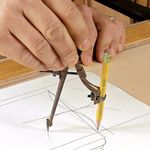
Compass
A necessary device for drawing circles and curves precisely. Additionally good for format.
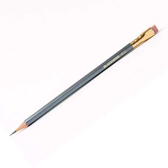
Blackwing Pencils
Should you’ve listened to Store Speak Stay, you’ve got heard them discuss extra about these pencils than you possibly can presumably think about.
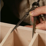
Dividers
Extremely helpful for laying out, setting equal distances, and evaluating measurements, these are a vital device for any furnishings maker.
Join eletters at present and get the newest methods and how-to from Wonderful Woodworking, plus particular provides.
")

")


")
